General:
Besides MMTTY and some other software packages Makoto (Mako) Mori, JE3HHT, has written MMVARI. This is a software kit which provides RTTY and various modes based on Phase Shift modulation in just one package. The approach is a very attractive solution for digital mode operations since switching between different modes can easily performed by a few clicks within the same frame. Our investigations of the use of MMVARI in TurboLog 4 have revealed a considerable effort for implementation since a bulky software environment of XML and Visual Basic components, i.e. OCX have to be enabled and to be added to the code. However, this burden and even a few impairments are by all means balanced by the technical performance of the detection algorithms designed and incorporated by JE3HHT. This finally lead to our conclusion to add MMVARI to the soundcard based digital mode facilities in TurboLog 4.
About Licensing:
We explicitly would like to express our gratitude to JE3HHT for providing MMVARI as a freeware tool kit. We herewith acknowledge JE3HHT's Terms and Conditions ( cited ):
"TERMS and Conditions:
=====================
(MMVARI Program & Help file)
MMVARI is freeware. The world wide copyright is held by Makoto (Mako) Mori - JE3HHT. MMVARI is released with no support or warranty. The author accepts no responsible and/or liability for damage that may be caused by the use of the MMVARI program."
.../...
If you distribute a commercial program, you can include code to use the MMVARI Engine in your software. However, you CAN NOT include MMVARI.EXE as part of your distribution..."
Since we only use code of the MMVARI tool kit and do not include MMVARI.EXE in our distribution the fore standing terms enable us to supply the package which we developed for use in TurboLog 4 within our version updates. Thus, unlike MMTTY the user must not load any software components from the internet himself.
About Installation of MMVARI:
The implementation of the MMVARI tool kit requires the installation of various components, most importantly an OCX plug-in. For ease of operation we have included the installation in our TurboLog 4 SETUP installation script. Unlike the standard TurboLog 4 components the OCX plug-in requires administrator rights on your machine. Furthermore, we need to mention that OCX remains resident on your machine even after TurboLog 4 was turned off. This should not be a problem. However, if you don't like this feature you can run the Custom Installation feature in the SETUP while updating and tick off the MMVARI package from installation.
Registering OCX under Windows:
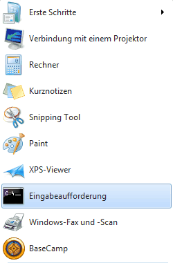
No specific registering is necessary under Win-XP since this is being done during the installation/update procedure. However, the recent Win-versions require administrator rights for registering. Unfortunately, the user himself is forced to perform this operation which is a bit awesome. The first step will be to open the administrator's command line which truly is a fallback into the old DOS times. You have to click the Windows START button which comes up in the bottom left corner. This is how it may look like ... of course in your language and with your customizations in Windows.

Figure 297: Activate Command Line Operation
In order to gain administrator's rights on your computer you need to select and click the command line item as shown above. If it should have been dropped from the short list shown it can be recovered by entering its name: CMD... in the entry line at the bottom. Another option to surface the command line is to: Press the WINDOWS + R keys simultaneously.
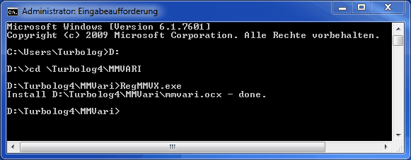
On the box which now opens the following interactive typing has to be performed ... assuming Turbolog4 is residing in HDD partition D: :

Figure 298: Administrator Control Box
Done .... ready to go!
By the way:
If you should want to remove the OCX package from your computer you would need to follow the same procedure as described above. However, with the administrator rights gained you need to enter in text line 5 after the prompt: RegMMVX.exe/U .
Implementation
The sound card based MMVARI facility is implemented within the framework of the Multimode Facility. Thus you should familiarize yourself with the basic principles of operating the Multimode Facility. Basically, the whole MMVARI package is just treated as another "device". Thus, the setup for MMVARI is part of the MultiMode setup. Consequently, you only need to move into the Configuration menu, select Devices and finally sub item Multimode Controller. You will have to select MMVARI from the Devices' drop down box and load the default Command/Script and Device Buttons. They are ready for use and should be fully sufficient for the immediate start of MMVARI operation. Furthermore, if you consider PTT control for your transceiver you need to select a COMport for this operation and edit Device Configuration > Settings as shown in the MMVARI topic of the Setup. This COMport can be identical to those used in the PSK31 and MMTTY facilities for PTT purposes.
The MMVARI control window:
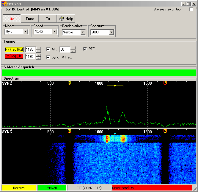
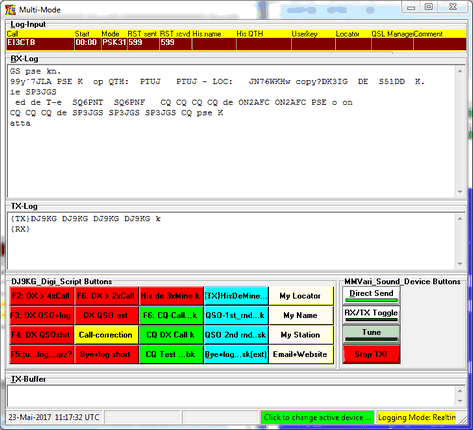
After you have correctly setup the MMVARI device you can start MultiMode operation from anywhere in TurboLog 4 by pressing the short cut Ctrl+D or from the Digi-/Multimode action menu upside the Logbook window. This will open two windows at the same time, the MM-Vari form and the standard Multi-Mode form. Both forms are depicted and described below:

Figure 299: MMVARI Layout in TurboLog 4, RTTY Operation shown
As will be noticed by comparing the MMVARI frame with the PSK31 frame both layouts have been designed to the largest possible similarity with respect to 'look and feel'. Allowing to do so is one of the strongest benefits of the MMVARI tool kit. However, there are considerable differences in the operational behavior. Thus, MMVARI's features are described in greater details below:
Always stay on top:
With this check box being ticked the MMVARI frame will always stay on top of all other open windows.
RX Indicator:
The yellow line array indicates the center of the receive frequency or tone pair. It can be moved by left mouse key click into the spectrum or waterfall display area to any position within the audio band on display.
TX Indicator:
The red line array indicates the center of the transmit frequency or the tone pair. It will be covered by the yellow line if Sync TX Freq is checked and transmit frequency equals receive frequency. With Sync TX Freq being unchecked Split Operation is invoked within the audio base band. Only(!) the RX line array can now be dragged or moved within the spectral display areas by left mouse key operation ( click or/and drag & drop ). However, the TX line array should have been movable. Unfortunately, this is one of the few deficiencies in MMVARI. See below in Getting started for an alternative operation.
ON:
Pressing this toggle switch button will turn the MMVARI facility on.
Tune:
Pressing this toggle switch button will turn the facility into transmit mode. The equivalent Device control button on the MultiMode frame is Tune. An unmodulated tone is generated which can be used for testing and tuning the transceiver.
Tx:
Pressing this toggle switch button will start transmitting. Narrow spaced tones in idle mode will be displayed while transmission is enabled.The equivalent Device control button on the MultiMode frame is RX/TX Toggle. The two tone signal remains unmodulated as long as no data is provided from Script buttons or entered directly from the keyboard into the TX buffer of the MultiMode window.
Help:
Opens this Help topic.
Mode:
This drop down box allows you to select all digital transmission modes which are implemented in MMVARI. For the time being the following modes are available:
GMSK
FSK
FSK-W wideband
BPSK
bpsk reverse
rtty-L LSB
rtty-U USB
mfsk-L LSB
mfsk-U USB
qpsk-L LSB
qpsk-U USB
Speed:
This drop down box allows you to select the common baud rates. The content of the box is assigned to the selected transmission Mode. The default is 45.45 Bd with RTTY.
Bandpassfilter:
Select from WIDE, MIDDLE, NARROW and ULTRA NARROW. Unfortunately, there is no noticeable effect. One of JE3HHT's little secrets... .
Spectrum:
Select the audio band width for display from this drop down box. The choice is between 250, 500, 1000, 2000 or 3000Hz. The default is 2000Hz. More choices can be defined in the Device Settings under the Devices menu.
RxFreq:
This thumb wheel allows fine adjustment of the numerical value of the RX receive frequency. Its label is on yellow background color in order to indicate its assignment to the receive frequency. Since thumb wheel action is rather slow you can also click into the box and enter a numerical value from the keyboard. Thus, large frequency offsets can be managed instantaneously.
TxFreq:
This thumb wheel allows fine adjustment of the numerical value of the TX receive frequency.Its label is on red background color in order to indicate its assignment to the transmit frequency. Since thumb wheel action is rather slow you can also click into the box and enter a numerical value from the keyboard. Thus, large frequency offsets can be managed instantaneously. This is the preferred method to set an initial frequency offset for Split operation.
AFC:
The automatic frequency control will tune receive frequency exactly on to the received set of tone carriers, if check box is ticked. The capture range can be adjusted by means of the thumb wheel button. Unfortunately, AFC control shows some sort of 'life on its own' in the RTTY operations. However, it works very well with the other modes. Another one of JE3HHT's little secrets... .
SyncTxFreq:
This control will synchronize receive and transmit frequency, if ticked. Uncheck, if you want to start Split operation.
PTT:
Checking this box will enable switching between RX and Tx via the output of a selected Comport instead of using the transceiver's voice control ( VOX Voice Operated Transmitting ). PTT Push to Talk switching should be preferred in order to prevent your rig from being triggered unintentionally by other output signals from the sound card. A comport has to be selected in Devices for PTT purposes. If there are no more comports on your PC you will need an USB to Serial Port converter or an external Multi Purpose Soundcard Interface device.
Serial port and PTTMode information is displayed in the Status bar, Panel 3 from left. By default the PTT switching signal is output on the DTR and RTS pins of a standard DB-connector. The signal is polarized as to pull down a switching transistor.
S-Meter:
This display will show the relative signal strength of the received signal.
Squelch:
This slider allows you to adjust the threshold for good signal detection and print quality. The squelch level can be reset to its default by right mouse key click into the slider bar. The squelch level may be predefined in the Devices settings. ( If wanted: It could also be controlled by suitable buttons from the Device button array of the MultiMode frame ).
Power spectrum:
The frequency range on display can be customized by the user (see item Spectrum above ). The power spectrum display is computed by means of a 2048 points FFT Fast Fourier Transformation. While the frequency axis is divided linearly the power axis is displayed at logarithmic units (by default). The frequency range on display can be moved by left mouse key clicking or dragging of the left or right sides of the spectral areas.
Spectrum waterfall display:
This fancy display allows to monitor spectral power density versus time. This is ideal for finding and tuning to signals and to monitor the signal to noise ratio during reception and transmission.
Status bar:
The status bar consists of 4 panels. The left panel [ logical 0 ] is used by MMVARI for the output of messages, such as:
Transmit
Receive
ON
OFF
Input Overload, etc.
The second left panel [ logical 1 ] shows the device's name ( MMVARI ) on green background color. This panel comes up if the PSK31 facility has been turned on.
Panel 3 from left [ logical 2 ] contains PTT COMport status information.
Finally, panel 4 [ logical 3 ] may be accessed by the user for display of customized messages defined under the Device Buttons.
Notch filter operation:
Multiple notch filters can be set by right mouse key clicking in the spectral display area over the frequency to be notched out. Clicking Set Notch in the upcoming little menu frame define the filter:

Figure 300: Notch Filter Menu
A small yellow button will be displayed as shown in the MMVARI Form above indicating the filter's position. You can see the high filter efficiency by the black traces in the waterfall display. Deleting a notch filter requires to position the mouse tip exactly on top of the yellow button until a small horizontal double-sided arrow comes up. Right mouse key clicking and then clicking Delete Notch will remove the filter which was placed at that position.
MultiMode window as adapted to MMVARI:
Digital mode in/output of data and control is implemented in the MultiMode form. There are ready-for-use scripts available under the Digi Script Buttons. A typical DX-QSO will just require to click the F2...-button for calling and the F3...-button for responding and logging the QSO. The screen shot below shows some sample data and the layout of the MultiMode window for use with MMVARI:
Please note:
Before you can send any text from the MultiMode frame you need to press the Direct Send button.
All details concerning editing the macro buttons are outlined in the Devices topic in the Digi Script button section. For ease of operation every button provides a tool-tip upon mouse over. This tip will show the complete script including placeholders, commands and text. This is well suited to remind you of the actions under a particular button in order to prevent you from sending text unintentionally.
You can edit the buttons on the fly with the MultiMode window in operation. Press Ctrl+S in order to open the setup and move into the Devices sub menu. Open the device you are currently operating. Click the button you want to edit and then Accept. The open MultiMode frame will now be updated and the edited script is immediately available on the button.
The Log Input line can fully be customized, i.e.be configured for Contest operations. This is described in greater details in the topic on Logging Modes and Contest Support.
The rightmost panel on the status bar of the MultiMode frame  allows you to change the active device on the flight.
Getting started:
There are only a few steps to perform for getting ready with MMVARI in TurboLog 4. These are:
1.Enable the MultiMode facility in the Devices section of the Log Setup menu.
2.Select MMVARI as the active device.
3.Select a COMport for automatic PTT operation.
4.Press Ctrl+D from the log page in order to open the MMVARI panel along with the MultiMode Window.
5.Press Start on the MMVARI frame and Direct Send from the MultiMode frame to begin operation.
6.Pressing the top left red button "F2: DX> 4xCall". You should see the text appearing in the TX-Log and the device should automatically switch into TX-mode, send your call 4 times and return to RX-mode.
7.Hovering the mouse over a button will surface the text it will transmit.
8.For Split operation: Tune to the transmit frequency of the DX station first, un-check the SyncTxFreq box, enter your desired TX frequency (...if within the audio band(!) ) in the TxFreq box; adjust future minor frequency offsets by the TX spin buttons.
ACTIVE COMMANDS:
KEYS:
| Ctrl+A | Selects all text in frame. |
| Ctrl+Delete | Deletes all selected text. |
| Ctrl+D | Opens the MultMode window. |
| Ctrl+S | Opens the Configuration menu for MultiMode setup. |
| Ctrl+Enter | Enters text from TX-Buffer into TX-Log. |
| Enter | Logs QSO. |
| Cursor+Down | ...from call field: Triggers DXCC analysis; sets Start time. |
| Shift+Cursor | Pushes text from TX Log into logging field. |
| Shift+CursorRight | Pushes text from TX Log into logging field. |
| Shift | Pushes text from TX Log into logging field. |
| Shift | Set Start time for logging. |
| Ctrl+X | Cut selected text. |
| Ctrl+C | Copy selected text. |
| Alt+ ... | User definable short cuts ... . |
| F1...F12 keys | User definable short cuts assigned to buttons. |
| Alt +F... keys | User definable short cuts assigned to buttons. |
| Shift+F... keys | User definable short cuts assigned to buttons. |
| Ctrl+F... keys | User definable short cuts assigned to buttons. |
BUTTONS:
| ON | In MMVARI frame starts the facility. |
| TX | In MMVARI turns device into TX mode with diddle ON. |
| TUNE | In MMVARI turns device into TX mode for tuning. |
| HELP | In MMVARI opens this Help topic. |
| Accept | Button on change active device frame, saves selection and closes box |
| Cancel | Button on change active device frame, closes box without any changes |
HOTSPOTS:
| Tool-tip | ... upon mouse over button. |
This topic was last edited on Thursday, 12-Dec-2024, at 13:30
