The Devices setup consists of the following sub items:
K1EL/WinKey ( ... its setup features are dealt with under the MultiMode Controller facility and discussed in WinKey Operation ).
Soundcard based Digital Modes ( ....are sub items of the MultiMode Controller facility ).
JT Programs, ( WSJT-X, JTDX )
All of these items are dealing with connecting external devices and/or PC-sound card based programs to TurboLog 4. They define COMports, interface parameters and handshake data. The setup is implemented by the editing of tab sheets. The tab sheets are placed in a frame which also contains the control buttons Apply, Accept, Cancel and Help.
==========================================================
The sub item Transceiver is accessed from the following tab sheet. Likewise, it can be reached by the shortcut Ctrl+T from everywhere in the program:
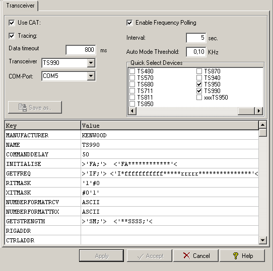
Figure 114: Tab sheet for Transceiver setup
As you can see more than just one transceiver can be selected from the drop down box.
A complete description of the various entries which can be made to this tab sheet is given in the topic Activating the CAT Facility. The checkbox Tracing should be checked in case of problems only. If checked the complete handshake between TurboLog 4 and your TRX will be recorded for later investigation. The path to the tracing file is as indicated in a separate topic on the CAT trace facility.
========================================================
The sub item TNC is accessed from the following tab sheet:
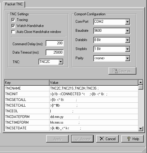
Figure 115: Tab sheet for Packet-TNC setup
This screenshot shows the typical setup for the TNC2x-family of modern TNCs. A complete description of the various entries which can be made to this tab sheet is given in the topic Connecting to Radio Clusters.
Please note:
If you have made changes to this tab sheet which require to press the Apply button an existing Packet connection will be disrupted because the Apply button closes and then reopens the COM-port. Best practice is to apply changes offline.
=======================================================
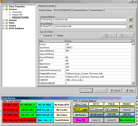
The setup for the MultiMode Controller facility is accessed from the Multimode Controller tab sheet which itself comprises of four sub tab sheets. In addition to this group, there is a floating Setup Buttons frame assigned to it:
In order to edit and/or inspect the tab sheet the Setup Buttons frame should be dragged off the center by mouse action with grip on the blue control bar.
All components of this assembly will be described in greater details below:
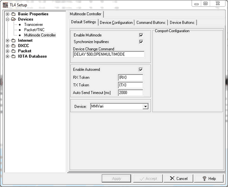
The top level tab sheet allows you to enable MultiMode operation as such, to select a particular device from a drop down list and to define the COMport and other parameters in order to control it. The entry fields are arranged as follows:
The following parameters can be customized by the user on this tab sheet:
Enable Multimode:
This box needs to be checked as indicated in order to enable the MultiMode facility.
Synchronize Inputlines:
Since the MultiMode page features a separate log input line the contents of both lines, this one and the one on the main window can be synchronized with respect to the content of the logging fields. Synchronizing means that all input fields that are not empty will be copied from one line to the other if you switch between them. This is a fancy feature which saves a lot of typing. Of course the logging procedures can be performed independently from each other in both windows.
Device Change Command:
This command controls changing between digital devices by clicking the Device Panel on the MultiMode control frame's Status Bar (... at the bottom of the frame). The delay is important for the time needed to remove the active device before the selected device is constructed and ready for display. The delay time is indicated in milliseconds. The necessary delay is depending on your PC's clock rate. 2000ms is a good value to start with. However, 500ms may be fully sufficient on faster machines. The command text should not be altered.
Enable AutoSend:
Mark this check box if you want to enable TurboLog 4's break-in capability from the keyboard for the digital modes/devices. This feature allows you to turn your rig on by striking any key with the character being transmitted immediately or appended to any text which is currently transmitted from the TX buffer.
RX Token:
The character string {RX} has to be included in macros in order to turn your rig into receive mode at the end of a transmission. It should not be altered by the user.
TX Token:
The character string {TX} has to be included in macros in order to turn your rig into transmit mode at the start of a transmission. It should not be altered by the user.
AutoSend Timeout:
This parameter controls the hold time of the transmitter after the last key was hit in break-in mode.
Device:
The type of MultiMode Controller has to be selected here. For the time being the following devices are supported:
•PTC-II
•PK-232/DSP
•KAM
•K1EL-Keyer
•PSK31_Sound (=sound card based internal software device for PSK operation, see below for more details)
•MMTTY_Sound (=sound card based internal software device for RTTY operation, see below for more details).
•MMVARI (=sound card based internal software device for RTTY, BPSK,QPSK, etc. operation, see below for more details).
Other controllers can easily be added to the list as long as the set of commands is provided. The command interpretation is depicted in the Script box at the bottom part of the tab sheet.
Selecting a particular device will automatically load the attached macros (=button definition files) when the Apply button is pressed.
Comport-Configuration:
The standard communication parameters for the serial interface to the Multimode Controller have to be entered as given in the example above. These are:
•A unique Comport, not otherwise used in your setup,
•The Baudrate,
•The Data bits,
•Parity check, odd, even or none as in the example,
•Stop bits.
If you are testing your interface you will be interested in monitoring the interface handshake which follows the same philosophy as in CAT and Packet operations. In this case the Tracing check box should be marked. The default, however, is unchecked.
Please note:
If you run more than one external/internal MultiMode device you will not like to adjust distinct Comport parameters which belong to them while you switch from one to the other. In order to ease this trouble you can edit the individual Settings (see next paragraph: Device Configuration ) in an entry as shown above, for example:
COMPORT COM1,9600,8,N,1
This entry will fix the inputs of the Comport Configuration and overrule in case of discrepancies!!
This tab sheet will allow you to customize button definition files, individually load them, editing scripts and commands and to finally save modified files for future use. If you want to customize files you should always start from the defaults and use Save as... to save your modifications under a self explaining file name. This one can then be loaded and will become your customized default provided the Apply button is pressed:
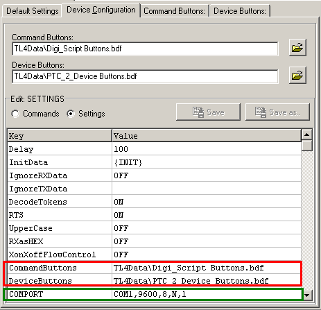
Figure 118: Device Configuration Tab Sheet
This tab sheet hosts the following controls:
Command Buttons:
The content of this box shows the name of the CommandButton definition file which was currently selected to be active. All button definitions are saved in TurboLog 4's ...\TL4Data sub directory. The file specification is .BDF . The user can create customized button definition files by opening the file dialogue box under the

button. This comes up as:
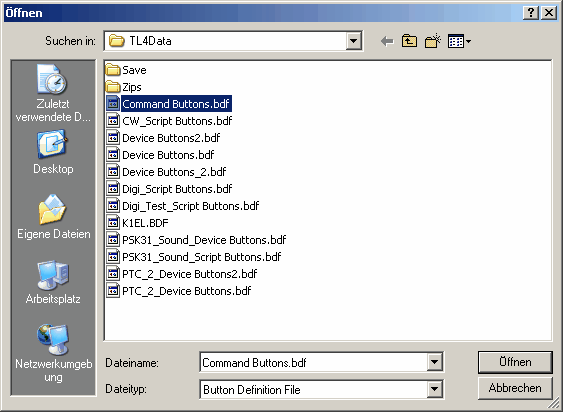
Figure 119: File Select Box for Button Definitions
The file select box shows all button definition files which are currently available under the ...\TL4Data directory.
The file CommandButtons.bdf is intended to be the default file to start with.
Please note:
If you want to customize any button files you will have to start from these factory defaults, modify to your needs and save the customized file under another suitable ( =retrievable/speaking ) filename. If you have already done this in the past you will have to load the customized file along with the selected device for which it was designed. In order to activate the button definitions just loaded in conjunction with the selected device on the Default Settings tab sheet you need to click the Apply button. This will save your compound in the script of the Device Configuration tab sheet as can be seen on the screenshot above. This has to be done only once. The next time you select a particular device, button definitions, COMPORT parameters and other saved features of the driver will be applied automatically.
You can also edit the buttons on the fly with the MultiMode window in operation. Press Ctrl+S in order to open the setup and move into the Devices sub menu. Open the device you are currently operating. Click the button you want to edit and then Accept. The open MultiMode frame will now be updated and the edited script is immediately available on the button.
Device Buttons:
In total analogy to the CommandButtons the content of the file select box also shows names of potential DeviceButtons definition files. DeviceButtons can be distinguished from Command- or ScriptButtons by their "speaking" names. The file DeviceButtons.bdf is thought to be the default in this context. DeviceButtons_2.bdf holds an extension set of additional device buttons which can be called from a suitably programmed button in the buttons's group box (see below for more details).
Save as... buttons:
These buttons will only become active if the Script Box was edited. Pressing the Save as ... button will allow you to save the device driver's set of commands and settings contained in the Script box for this particular device. Thus, a file dialogue box opens to show:
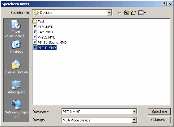
Figure 120: Save Device Definitions
As can be seen the file specification for the drivers of the MultiMode devices is .MMD . All files need to be stored in the ...\Devices sub directory of TurboLog 4. Press Save if you want to save your changes or Cancel to close the box without applying any changes.
Editing the Tab Sheet's Script boxes ( Items: Commands and Settings ):
1. Commands:
This box containing the command scripts is initially being displayed . The left column of the box contains the generic expressions as used for the commands and messages under the buttons. These expressions can be enclosed in braces { } and used as controls embedded in message scripts or directly under the buttons of the MultiMode Facility. The right column contains the specific character strings "known" to the device and interpreted by it in order to perform a particular control action. This approach allows to define generic command strings and thus to become independent from any real device. The syntax of the generic commands is described in greater details along with the setup of the CommandButtons as described below.
You can include more commands if necessary to the default set at any time. This, however, must be done with reference to the operating manual of the specific device. In order to create a new, empty line you need to move to the bottom line of the table. Pressing Cursor+Down will add a new line which can be edited as required. The sequence of the command definitions is irrelevant.
2. Settings:
Clicking the radio button for the Settings will allow to edit them ( see screenshot above ). The parameters defined under Settings are important support variables of general use for adapting to the devices and their specific properties. The set of variables available is defined as follows:
Delay [ ~ ] |
100 |
One ~ introduces a delay of 100 ms |
InitData |
{INIT} |
Executed on Opening the Device, details specified under Commands |
IgnoreRXData |
OFF |
Received handshake data will not be displayed |
IgnoreTXData |
.... |
Filtering out data sent to the device and suppressing its display in the TX-Log |
DecodeTokens |
ON |
Allows for applying: <, >, etc. |
RTS |
ON |
Ready to Send terminal status, ON by default |
UpperCase |
OFF |
All letters are changed to upper case |
RXasHex |
OFF |
All content of enclosures in <...> changed to hex data |
DeviceButtons |
.... |
Desired file to be loaded for the device containing specific Device Buttons definitions, other than default |
CommandButtons |
.... |
Desired file to be loaded for the device containing specific Command Buttons definitions, other than default |
XonXoffFlowControl |
OFF |
Software handshake is OFF by default |
Xon |
.... |
Received string to be interpreted as Xon |
Xoff |
.... |
Received string to be interpreted as Xoff |
COMPORT |
COM1,9600,8,N,1 or e.g.: -,1200,8,N,1 |
This entry will overrule entries in the Comport Configuration; In the second example the port default will be read from the Comport Configuration group box since it is not specified here : ( - ) |
SendDelay |
0 |
Delay in ms |
Table 9: MultMode Communication Parameters
Command buttons are provided for ease of fast transmission of digital data. Standard text modules as used during a QSO can be transmitted by pressing just one command button. Moreover, control strings can be included in the text as to provide a magnitude of operational benefits. All of that makes QSOs in digital modes fast and easy.
Clicking into the Command Buttons tab sheet will show an empty sheet on the first glance. Its entry fields, however, become filled on interaction with the Setup Button frame. This requires to select a button in the Setup Button frame by clicking on it. If, for example, the top left button is clicked (F2: DX>4xCall ), the tab sheet's fields will show the following contents ( example shows CommandButton definitions for PSK_Sound ):
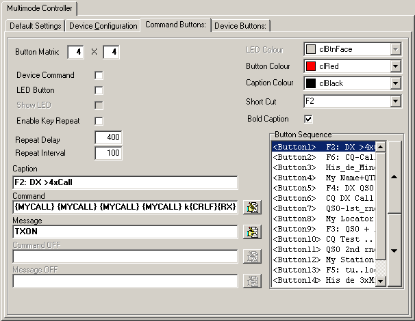
Figure 121: The Command Buttons' Tab Sheet
The controls and entry fields are to be used for the following purposes:
Button Matrix:
Enter the matrix dimensions in these boxes. The format is: Columns x Rows. You can define a virtually unlimited number of buttons. The size of your screen, however, and the other fields required in the MultiMode windows will set a technical limit.
Please note: After you have modified the Button Matrix you should always click the Apply button in order to save your new configuration before you continue modifying items.
Device Command:
This box has to remain unchecked in case of a command button. It needs to be checked only if the script under the button serves as a control for the external device ( DeviceButtons ).
LED Button:
There are two types of buttons in the MultiMode window:
1.:The normal push-buttons for hosting text modules (= Macros).
2.: Buttons being equipped with a LED ( DeviceButtons ) in order to signal the control status of the external device.
Show LED:
Check this item in order to surface the LED feature of the button ( Not applicable here, for DeviceButtons only; see below )
LED Color:
Allows to define the LED color in case of a LED button ( not applicable for the CommandButtons ). The LED color can be selected from the thumb wheel to the right of the field.
Enable Key Repeat:
Check this item if you want to enable the key's repeat feature. If a key is clicked it appears as being pushed down. It will repeat its message as long as it is kept in this position. This will allow you to transmit a virtually endless string of characters.
Repeat Delay:
The time in milliseconds determines the restart of the sequence stored under the button. Of course this time must be compliant to the speed of transmission of the particular digital mode and the length of the string.
Repeat Interval:
This time in milliseconds determines the pause between repetitions.
Button Color:
The background color of the button's surface can be selected from the thumb wheel to the right of the field. This is a nice feature for grouping and organizing the functions stored under the buttons.
Caption Color:
The color of the button's caption can be selected from the thumb wheel to the right of the field.
Bold Caption:
Check this item if you want to appear the button's caption in bold characters.
Button Sequence:
If you select a button you can move it up- and downwards the list by means of the thumb wheel buttons to the right side of the box. If you rearrange the button array you need to be aware of its matrix structure. The appearance on the list is from left to right along the rows, starting with the element of the top left corner as the first element. We recommend you keep the button arrays in the Setup Button frame visible on the screen in order to assist you in selecting the correct buttons while moving them around.
Please note: You should always monitor the results of your operations by clicking the Apply button on the control panel just below the tab sheets. This will also save your new configuration before you continue.
Short Cut:
The drop down box assigned to this feature allows you to select a Short Cut or Hot key to the button under edit. The following Short Cuts are available:
F2 ... F12,
Ctrl+F2 ... Ctrl+F12,
Alt+F2 ... Alt+F12,
Shift+F1 ... Shift+F12
Thus, there is a total of 44 short cuts available which can be assigned to Command and/or Device Buttons by the user. The F1 key cannot be made available since it is globally reserved by WINDOWS for the HELP system.
Please note:
You need to make sure yourself as to assign the same short cut just once. Multiple assignments may yield weird results and will never activate one button after the other.
Caption:
You can enter the caption of the button into this field. The caption should be "speaking" such as to instantaneously remind you of the text module behind it.Furthermore, if you are interested in operating the buttons via hot keys you only need to start the caption string by an &. Thus, if you wanted to name a button Go and you enter the caption as &Go the button's caption will show up as Go. This button can now be commanded by pressing Alt+G. Be aware, however, not to interfere with key strokes reserved by WINDOWS. In other words: This feature should be restricted to a few buttons only. As outlined above you can also assign other customized short cuts to the buttons.
It is good practice to indicate the short cut assigned to a button in its caption. This will help to remind you of the assignments you made even in the heat of a fierce DX-fighting.
Please note:
On Mouse Over a button a tool tip will be displayed. It shows the script under the button and eventually an assignment to a short cut.
Command:
This is the field for entering the text to be transmitted if you push the button. You can enter plain
text and include placeholders and command sequences. Placeholders and command strings need to be placed in braces { }. The brackets always indicate: Content needs to be interpreted and will not be transmitted over the radio. All commands are case insensitive. In case the original field of the placeholder should be empty there will be inserted nothing , not even a blank.
The following place holders are available:
| {MyCall} | This is your ...licensed... call. |
| {MyName} | Your name as entered in the log's configuration. |
| {MyQTH} | Your QTH as entered in the log's configuration. |
| {MyLocator} | Your locator as entered in the log's configuration. |
| {LF} | Forces a linefeed. |
| { } | Inserts blanks, e.g. at the end of a line, etc.. |
| {UTCTIME} | Inserts the time formatted as: hh:mm:ss UTC . |
| {Daytime} | Inserts: GN if system's UTC-time is within 00 to 06 hours; GM=06-12z, GA=12-18z, GE=18-24z, respectively. |
| {Exchange_Sent} | Inserts your contest exchange to be sent; this field must be available on the log input line. |
| {Exchange_Rcvd} | Inserts the received contest exchange; this field must be available on the log input line. |
Besides this all fields from the log input line can be inserted as placeholders by using their name as defined. The following will be useful, in particular:
| {CALL} | His call, as entered in the Call field some time before referring to it. |
| {RST_sent} | His RST. |
| {His_Name} | His name. |
| {His_QTH} | His QTH. |
| {Band} | Band of operation. |
| {Mode} | Mode of operation. |
etc., etc. ...
The following command strings ... oriented towards the device and interpreted by it .... are of great operational benefit:
| {TX} | Turn the external device into transmitting mode. |
| {RX} | Turn the external device into receiving mode. |
Besides these commands you can use others as defined in the script box's left column ( see the Device Configuration for more details).
All short scripts can be entered in the input line itself. In case of bulky text the editor icon to the right of the input line:
![]()
can be clicked in order to open a simple text editor ( memo field ). The following is a sample of text which should better be edited in the box... for ease of operation:
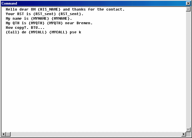
Figure 122: The Command Button Script Editor
The editor will insert the necessary carriage returns and linefeeds automatically. Please always keep an eye on the end of the block of text whether you want another line feed to appear or you want to continue with manual typing ...eventually.
Please note:
The editor box can handle overall script lengths of up to 256 characters ... for the time being.
A system control message to be distributed in TurboLog 4 could be included here. The message handler in TurboLog 4 will take care for distributing the message(s) to the correct receiver which in turn will perform the desired action. Of greatest operational benefit is the following message:
| {InputlineMulti}LogQSO | This system command message will log the QSO. |
This allows to transmit a final message to your QSO-partner and simultaneously log the QSO. Most beneficial applications of this feature are demonstrated for the Bye Bye -message button and for the fast DX-QSO or contest logging.
Automatic logging can be prevented from being executed immediately after the message is released by introducing a suitable delay to this operation. For example:
| Delay 3000;{InputlineMulti}LogQSO | This compound of system command messages will result in the QSO being logged at 3000ms ( = 3s ) after the button was pressed. |
For fast CW-operation using the K1EL-keyer it will be desirable to keep the input focus e.g. on the CALL field i.e when short cuts are pressed or command buttons activated. This feature can be customized by applying the following message:
{InputLineMulti}SETFOCUS CALL
Likewise you can select another valid field name of the loginput line ... according to your habits. There is no need, however, applying this command with "true" digital-mode devices such as the PTC-II. The focus management is optimized by default for QSO data that needs to be extracted from the RX-Log of the MultiMode facility.
Command OFF:
Only applicable in case of LED buttons.
Message OFF:
Only applicable in case of LED buttons.
DeviceButtons are provided for ease of direct communication with the external digital MultiMode device. Unlike the CommandButtons all text is to be interpreted with respect to the generic set of commands as needed to control the device. Thus it has to be put into { } braces. Typical control actions are:
•Set device to TRANSMIT or RECEIVE mode,
•select digital mode such as RTTY, PSK31, etc.,
•RESET device,
•Etc....
All DeviceButtons are implemented as LED buttons with static On and OFF positions. Thus, each button can forward an ON-message and an OFF-message to the device and/or to the message handler in TurboLog 4. More details are outlined by means of the following screenshot which shows the scripts behind the mode button for RTTY (...for the PTC-II device ):
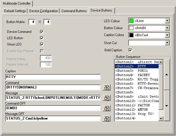
Figure 123: Device Buttons's Tab Sheet
Since the DeviceButtons tab sheet and the CommandButtons tab sheet have common elements and controls only differences will be touched in the following description:
Device Command:
This box has to be checked in case of a DeviceButton.
LED Button:
This box has to be checked in order to enable the LED features.The LED's color is intended to signal the control status of the external device.
LED Color:
Allows to define the LED color. The LED color can be selected from the thumb wheel to the right of the field.
Caption:
The caption of the button is RTTY in this example. Pushing this button must turn the device's mode into RTTY. Simultaneously the LED should be turned to green light.
Command:
The generic command to the device is simply RTTY ( normal polarity ). Internally this "speaking" command may be translated into a notation the selected device will understand ( to be defined in Editing the Script Boxes: Commands, see above ).
Message:
A number of most valuable features can be commanded and customized by entering the suitable commands into this field. Among those fancy features are the following sample cases:
•Send a message to the status bar of the MultiMode window,
•Set Mode in the loginput line,
•Load another group box of buttons,
•Enable Direct Sending,
•etc. ...
Case 1:
The example screenshot shows the following message string:
STATUS_2 RTTY|clred;{INPUTLINEMULTI}MODE=RTTY
This string actually consists of two commands separated by a ; . The first command will write the word RTTY on red background color into panel two of the status bar at the bottom of the MultiMode window.
Case 2:
The second part is a system control message which addresses the log input line of the MultiMode window and will set the content of the Mode field to RTTY.
More system control messages to be distributed in TurboLog 4 could be included here if they are separated by a ; . The message handler in TurboLog 4 will take care for distributing the message(s) to the correct internal handlers which in turn will perform the desired action.
Case 3:
Another interesting technique is applied under the device button:

The message under this button is:
{RTTY_ButtonFrame2}RELOADBUTTONS FILE=TL4DATA\DeviceButtons_2.BDF
This message allows you to extend your set of Device Buttons by switching to another array of buttons as defined in the file: ...\TL4DATA\DeviceButtons_2.BDF
This allows you to switch to another group box of buttons instead of defining a larger array of buttons. This may be beneficial on small screens in particular.
Case 4:
Of course there must be a way back to the first group box. Thus the called box must have a "return" button. Its outline e.g. could be:

This button exhibits the message:
{RTTY_ButtonFrame2}RELOADBUTTONS FILE=TL4DATA\DeviceButtons.bdf ,
if the main group box was defined under: ...\TL4DATA\DeviceButtons.bdf .
Case 5:
If you want to enable toggling between Direct Sending and buffered transmission by bypassing the Transmit Buffer (case 1) or sending from the buffer you need to define a suitable button to facilitate this task. An example is shown in the screen shot of the MultiMode Setup Assembly ( see above ). The message under the button in this case simply reads:
DirectSend ON .
Likewise, the script in the Message OFF field must read:
DirectSend OFF .
Command OFF:
This entry specifies the command which has to be sent to the device as the LED button is released for return into its OFF status. The example shows the command {CMD} which is interpreted as <ESC>PT| by the device since the command was defined this way in: Editing the Script Boxes: Commands ( see above ). This will turn the internal status of a PTC-II multimode device into "neutral" mode.
Message OFF:
The LED buttons allow sending an OFF-message for various purposes.
The message:
STATUS_2 Cmd:|clyellow
as shown in the example will write the word Cmd: on yellow background color into panel two of the status bar at the bottom of the MultiMode window. Please also note the application described under Case 5 above.
As for the CommandButtons all scripts can be entered in the input line itself. In case of bulky text the editor icon:
![]()
to the right of the input line can be clicked in order to open a simple text editor ( memo field ). This editor is well suited to format your text in a straight forward way.
Please note:
Copying of text from one's button definitions to the other's should always be performed from one's editor box to the other's.
=======================================================
Soundcard based Digital Modes:
Soundcard based digital Modes such as RTTY or BPSK and its derivatives are embedded in the MultiMode Controller environment. Thus, for ease of operation these modes are just another choice of a dedicated device on the Default Settings Tab sheet.
If you decide to run PSK31 ( or BPSK or QPSK ) by means of your PC's sound card you only need to select the Device item PSK31_Sound as indicated below:
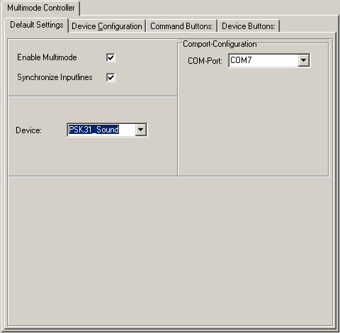
Figure 124: PSK31: Soundcard Configuration Tab Sheet
Selecting this "device" will automatically:
•Initiate the soundcard
•Load the PSK31.DLL
•Load a dedicated default set of internal command definitions ( ...as defined on the Device Configuration tab sheet )
•Load a dedicated default set of settings ( ...as defined on the Device Configuration tab sheet )
•Load a dedicated default set of CommandButtons and DeviceButtons ( see appropriate tab sheets for access and customization )
•Open the selected Comport for the PTT control of your transceiver ( as defined under the item: Comport Configuration; see above ).
We assume the default sets of Command and Device buttons to be fully adequate for starting soundcard based PSK31 operation. Thus, you should refrain from applying any modifications until you have become familiar with the facility.
However, both button definition files can be customized. As described above, you will have to proceed to the appropriate tab sheets for the CommandButtons, DeviceButtons and Device Configuration, respectively, in order to apply suitable modifications.
Furthermore, you need to make sure the selected Comport can be uniquely used by the PSK31.DLL while it is activated. The Comport will be used for PTT-operation of your transceiver only. A suitable output from the device is available on the RTS and DTR pins of the serial interface. However, in case of no more Comports available you can still operate the VOX control of your rig.
Please note:
If you run more than one external/internal MultiMode device you will not like to adjust the required distinct Comport parameters attached to the device while you switch from one to the other. In order to ease this trouble you can edit the device Settings ( see above paragraph on: Device Configuration, green frame in the Settings script ) by applying/modifying the entry as shown above, for example:
COMPORT COM1,9600,8,N,1
This entry will fix the inputs of the Comport Configuration and overrule in case of discrepancies!!
The setup of the Device Buttons and Command Buttons is identical to the procedures as described for the adaptation of any other hardware device ( see above for full details). There are, however, a few specific commands and messages for the control of the PSK31.DLL to be explained here.
Messages to the DLL must include a specific header in order to allow the internal message controller to correctly assign a message to a distinct device. Thus, the PSK31.DLL can be controlled by the following messages:
| {PSK31}PSKON | turns the soundcard based PSK31 device ON. |
| {PSK31}PSKOFF | turns the soundcard based PSK31 device OFF. |
| {PSK31}TUNEON | turns the device into tune mode. |
| {PSK31}TUNEOFF | turns the tune mode OFF. |
| {PSK31}TXON | turns the device into transmit mode. |
| {PSK31}TXOFF | turns the transmit mode OFF (... not to be used to terminate transmit scripts/macros )! |
| {PSK31}PSKSquelch nn | move squelch slider to nn ( nn = 0...99 ) |
| {PSK31}PSKMODE n | select transmit mode ( n = 0...8 ) |
0 = BPSK31
1 = QPSK USB
2 = QPSK LSB
3 = BPSK62.5
4 = QPSK62.5 USB
5 = QPSK62.5 LSB
6 = BPSK125
7 = QPSK125 USB
8 = QPSK125 LSB
| STATUS_2 | |clBtnFace | will clear panel 3(!) from left on the PSK31FORM's status bar ( ... it is filled with blanks on grey background ). |
All other general messages as described above can be used under the buttons as well.
Specific Commands to be used in scripts and macros are:
| {RX} | turns device into receive mode ( ... to be used at the end of transmit scripts/macros )! |
| {CWID} | keys {MYCALL} in CW mode if inserted in the string. Keying speed can be adjusted in |
| the Turbolog.ini file, section [PSK31Settings]. |
| CW ID Speed selector code: |
1 = 37.5 wpm.
2 = 18.75 wpm.
3 = 12.5 wpm.
4 = 9.375 wpm.
All Placeholders as listed above can be used in the scripts for the PSK31.DLL device as well.
The default set of Device Buttons and Command Buttons ( PSK31_Sound_Device Buttons.bdf and PSK31_Sound_Script Buttons.bdf ) will most likely cover most user's needs. However, they can easily be customized and saved for future use according to the procedures as described for the generic MultiMode device ( see above ).
Please note:
We strongly recommend to use an interface between sound card and transceiver in order to isolate ground potentials and to prevent noise loops.
=========================================================
Unlike the PSK DLL, MMTTY is an executable program which is remotely controlled by TurboLog 4. This means that MMTTY is started and closed by TurboLog 4. Both programs communicate via a software interface. MMTTY is a sophisticated program which allows sound card based RTTY operation. Thus, MMTTY is treated as just another external MultiMode device. It is fully embedded in TurboLog 4's standardized control interface for the digital modes.
In order to run MMTTY you first have to download the engine from JE3HHT's ( Mr. Makoto Mori's ) website at:
http://mmhamsoft.amateur-radio.ca/mmtty/
MMTTY is provided free of charge. However, according to JE3HHT's licensing conditions every user must download directly from the official distribution site. Thus, we cannot attach the program to the TurboLog 4 installation package. The download package is named mmtty-engine165B.zip . We recommend to unzip MMTTY.EXE and to copy it into TurboLog 4's root directory. However, any other directory is ok as well as long as the path is defined in Device Configuration, section Settings. The path name is marked by the red arrow in the screen shot below. In order to see the depicted screen below the device:
MMTTY_Sound
has to selected and the MultiMode item to be checked on the Default Settings tab sheet.
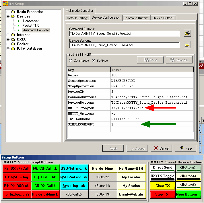
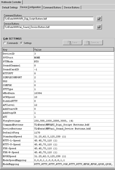
Figure 125: MMTTY Device Configuration and Button Layout
There is no need to care for MMTTY's PTT-Comport control in the MultiMode setup. Consequently, Simplecomport=2 indicates there is no active Comport defined here( see: green arrow ).
Please note:
The PTT-Comport must be defined in MMTTY's own setup menu only, item Option(O)--->Setup(O) ( see topic: Soundcard Based RTTY ).
This port may be identical to the definition for the PSK31_Sound device since only the output pins for:
RTS ( Ready To Send ) and
DTR ( Data Terminal Ready )
are used for switching purposes. For convenience each one(!) of these pins can be used.
All other items are standard settings and do not need any special attention at the beginning. The button definitions ( Macros) are well suited to start with. They can be extended and customized. The initial button configuration includes 4 spares which can be loaded with suitable text. Customizing is identical for all MultiMode devices and described in greater details in the MultiMode Controller section above.
Please note:
If you are annoyed by the stay-on-top behavior of the MMTTY control panel you can extend the MMTTY_Options in the Settings item at the value column above to read: -r -a ( minus r blank minus a ).
====================================================
Unlike the MMTTY and PSK31 facilities described in the fore standing paragraphs MMVARI consists of a dedicated, complex XML and Visual Basic software environment. The executable program MMVARI.exe is embedded in this compound. Following the general implementation philosophy for all Multi Mode Devices in TurboLog 4 the device's application is controlled by the standard MultiMode window.
Unfortunately, the installation of the complex software environment is rather demanding. However, there is not much we can do about it from the TurboLog 4 side.
The installation procedure is described in the main topic on MMVARI. After the installation was successfully completed the user only needs to select the item MMVari from the following Setup tab sheet:
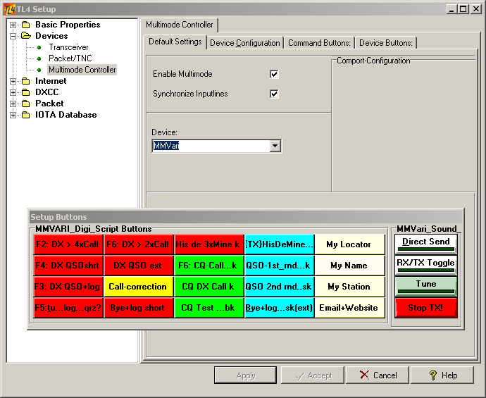
Figure 126: MMVari Main Tab Sheet Configuration and Button Layout
The most important user related parameters of MMVARI can be inspected and adapted in the Device Configuration tab sheet, item Settings:
Parameters of user concern are described below:
Command Buttons:
Path to the default macro script buttons for MMVARI with Load, Save and Save as... options.
Device Buttons:
Path to the default device control buttons for MMVARI with Load, Save and Save as... options.
Freq Settings:
Default width options for the spectral displays in Hz. The number in braces denotes the default item's position.
PPT Port:
Defines the COM port for the PTT control operation of the TRX. It may be the same as in PSK31 or MMTTY.
PTTMode:
Define switching: RTS line.
SoundCardID:
-1 is Window's default.
RTTYFFT:
Select type of RTTY demodulator: 0=IIR, 1=FFT
UOS:
Unshift On Space; 1=true.
COMFSK:
FSK output via the selected PTT COM port; the default 0 yields no, FSK output on the TxD pin of the PTT Port.Setting 1 will yield FSK output.
FFTType:
Amplitude representation of FFT displays; 0= [dB], 1= squared amplitude.
wModGain:
Digital output level, 0 to 32768.
wCWSpeed:
Speed of CWID [10 to 60].
DiddleRTTY:
0=LTR, 1=BRK.
AFCLevel:
Intended to control AFC behavior.
AddStartCR:
Add CRLF on start of transmission: 1=yes, 0= no
AddStopCR:
Add CRLF on stop of transmission: 1=yes, 0= no
ATC:
Automated Timing Control, Off at RTTY
DefaultFreq:
Default lower tone frequency: 1170Hz.
Standard Speed:
Default speed settings for the various BPSK-modes in MMVARI. The number in braces denotes the default item's position.
RTTY-L-Speed:
Default speed settings for the RTTY-L mode in MMVARI (L=Lower sideband). The number in braces denotes the default item's position.
RTTY-U-Speed:
Default speed settings for the RTTY-U mode in MMVARI (U=upper sideband). The number in braces denotes the default item's position.
FSK-Speed:
Default speed settings for the FSK mode in MMVARI. The number in braces denotes the default item's position.
FSK-W-Speed:
Default speed settings for the FSK mode in MMVARI. The number in braces denotes the default item's position.
BPSKSpeed:
Default speed settings for the various PSK modes in MMVARI. The number in braces denotes the default item's position.
ModeSpeedMapping:
This line controls speed-depending extensions on the modes available in MMVARI ( e.g. PSK31, PSK63,... ). A renaming is necessary in order to cope with the 'official" mode names being recognized by LoTW to count for DXCC.
The fixed order of the 11 modes currently 12/12/2024 implemented in MMVARI is:
GMSK, FSK, FSK-W, BPSK, bpsk, RTTY-L, RTTY-U, MFSK-L, MFSK-U, QPSK-L, QPSK-U,
The position showing a "1" indicates a mode which needs to be renamed and provided with a speed depending extension in order to become DXCC-worthy. For example: The "1" at the fourth position will automatically turn BPSK into PSK31, PSK63, PSK125 or PSK250.
ModeMapping:
This line controls the generic mapping of mode names in MMVARI to DXCC-worthy notations, e.g. GMSK is mapped on RTTY, FSK is mapped on RTTY and BPSK is mapped on PSK.
Of course you can customize the macro scripts under the Command buttons for your individual needs. However, we recommend editing of the Device buttons for the experienced users only.
As in the other soundcard based devices the following tokens are available in order to control the transmit/receive operations embedded in the macro scripts:
{TX}
Switches the PTT to transmit mode.
{RX}
Switches the PTT to receive mode.
{CWON}
Switches transmission mode to CW for the following characters, e.g. for sending a CWID.
{CWOFF}
Switches CW transmission mode off and reverts to selected mode.
Besides this the following Message Controller commands are implemented:
MMVariON
Turns the MMVari device to ON.
MMVariOFF
Turns the MMVari device to OFF.
TXON
Turns the MMVari TX button to ON.
TXOFF
Turns the MMVari TX button to OFF.
TXSTOP
Emergency STOP, MMVari device is turned to OFF.
TUNEON
Turns the MMVari TUNE button to ON.
TUNEOFF
Turns the MMVari TUNE button to ON.
MMVariMODE nn
Turns MMVari mode to: 0=GMSK,1=FSK,2=FSK-W,3=BPSK,4=bpsk,5=RTTY-L,6=RTTY-U,7=MFSK-L,8=MFSK-U,9=QPSK-L,10=QPSK-U,
MMVariSQUELCH nnnn
Switch MMVari Squelch control level; nnnn = 0..2048 (in units of 1/100 dB , e.g. 300 equals 3 dB)
CWON
Switches MMVari to transmit text as CW.
CWOFF
Switches MMVari back to transmit in the mode selected on the control box.
The work on customizing the Setup is finished by applying the suitable common tab sheet control button, see below.
==========================================================
This is where to set up the antenna rotor facility. The user interface to it and operational aspects are outlined in the paragraph Antenna Rotor Control.
We follow the command standard which was originally defined by YAESU for their rotor model GS-232A and adopted by EA4TX in his hardware interface box. This small device provides means to adapt to the majority of rotors on the market. The interface will convert digital commands provided by TurboLog 4 into switching actions for the rotor control and power supply unit.
Of course, in order to benefit from TurboLog 4's rotor control facility your rotor must provide a remote control connector which allows its operation from a separated control unit. Furthermore, the rotor control requires a unique COMport on your PC. Since modern PCs do not have COMports any longer you can either use an USB to COMport converter or install a driver which emulates a COMport via an USB port. The latter approach is anticipated by EA4TX in his interface installation. A suitable driver can be installed from the CD which comes with the hardware. The CD also contains the installation guide.
After you have successfully passed all basic installation steps we recommend to test the link between your PC and the rotor unit by means of a simple terminal program, e.g. HyperTerm, TeraTerm ( this one is included on EA4TX's CD ) or similar utilities. The manual provided by EA4TX includes all details how to do it, i.e. the simple commands which have to be transmitted. If you succeeded to control your rotor from a terminal program you can be sure to run the rotor facility from TurboLog 4 as well.
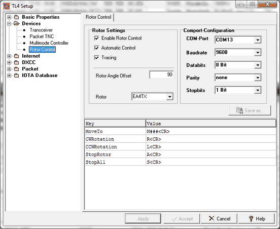
Next and in order to use the Rotor Control you have to set up this facility in TurboLog 4's Configuration menu by editing the following tab sheet:
Parameters of user concern are described below:
Rotor Settings:
Enable Rotor Control:
This check box needs to be ticked on if you want to enable the rotor control facility.
Automatic Control:
With this box being checked the rotor will automatically start turning on change of the bearing derived from a valid Call on the Call field. Turn this feature off if it does not meet your operational habits.
Tracing:
Check this box if you want to monitor communication between PC and rotor interface by means of the Trace Facility.
Rotor Angle Offset:
If you have mounted the rotor on your antenna tower with the turning point (e.g. 0°/360°) not aligned to geographic North you can enter the offset angle here. An offset to the East is defined as positive. Thus, for example, if your rotor's turning point is exactly pointing to geographic East you will have to enter: 90
Rotor:
Enter the name of your rotor or the type of the control interface here. The default is EA4TX.
COMport Configuration:
COM-Port:
As pointed out above you need to select a unique COMport for the rotor control. This can either be a real hardware port or a suitable USB emulation.
Baudrate:
The default as requested by EA4TX's interface is 9600 Baud.
Databits:
Default and standard is 8 bits.
Parity:
Default and standard is none.
Stopbits:
Default and standard is 1.
Key/Value:
This table contains the command definitions which TurboLog 4 uses internally ( Key ) and which the interface understands ( Value ).
This concludes all entries to this tab sheet. The work on customizing the Setup is finished by applying the suitable common tab sheet control button, see below.
======================================================
As described in the paragraph on JT-Modes Interface and Support TurboLog 4 in greater details users can benefit from the great performance of the digital Modes created and implemented by Nobel laureate Joe Taylor/K1JT ( also dubbed JT Programs ). This is the setup for the interface to his genuine program WSJT-X and for the clones ( e.g. JTDX ) which were derived from it:
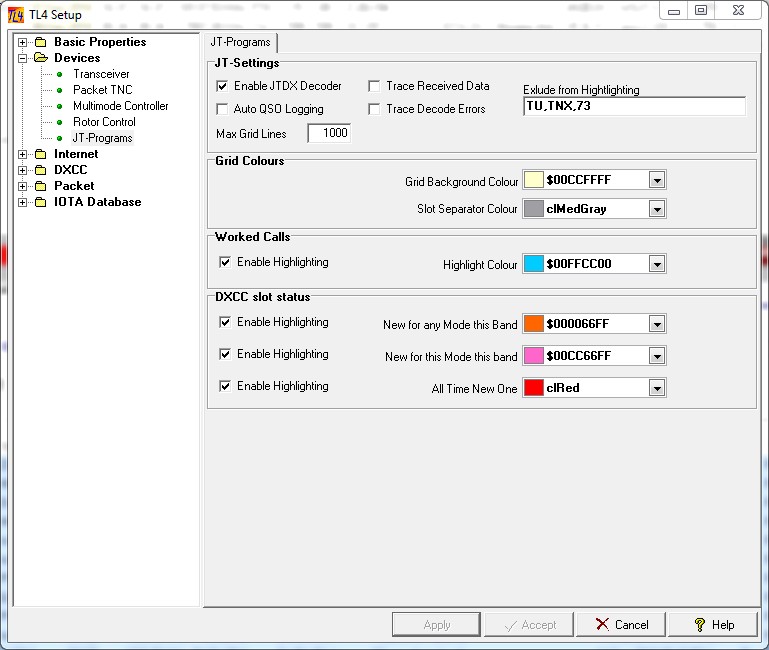
Figure 129: Setup for the JT Programs, WSJT-x, JTDX, etc.
JT Settings:
Enable FTDX Decoder:
Check this item in order to activate the interface to the JT Programs.The default is checked.
Trace Received Data:
Check this maintenance item in order to activate tracing and recording of data. The default is unchecked.
Auto QSO Logging:
When checked the log data generated in a JT program will directly be written into the TurboLog 4 logbook as soon as you are prompted upon completing a QSO. The default is checked.
Important notice:
In case you select manual logging the log data from the shell will be intermediately entered into the LogInput line. This allows you to enter additional data to the log record before you press the Enter key for logging, e.g. Name, QTH, QSL details etc.. Unfortunately, in order to enter the LogInput line you will have to click into it, e.g. on the Call field which already has been focused and highlighted for this purpose. This additional click is annoying. However, WINDOWS does not allow us from inside TurboLog 4 to pull focus control away from an external program, e.g. WSJT-X or JTDX. Thus, window and focus control have to be moved by the user's manual interaction only.
Trace Decode errors:
Check this maintenance item only in order to activate tracing of decode errors. The default is unchecked.
Exclude from Highlighting:
Enter words or fragments here which might cause false highlighting because they contain the Prefix of a DXCC country.
Max Grid Lines:
Enter a reasonable number of lines to be kept in the Adjunct Band activity Box. 500 to 800 lines should be sufficient in order to record the band activity of the last 30 minutes or so.
Grid Colours:
Grid Background Colour:
You can customize the background color of the Adjunct Band activity Box. Please pay attention to a good contrast to text and highlight colors.
Slot Separator Colour:
You can customize the color of the separator bar here.
Please note:
The following highlight colors will also effect Packet Spot Highlighting. The highlighting colors should be selected carefully with respect to conspicuity and good readability. Furthermore, the contrast to the text contained in the highlighted field must be maintained.
Worked Calls:
Enable Highlighting:
The default is checked.
You can enable highlighting of Calls in the Adjunct Band activity Box if they are 'known' by TurboLog 4 which means the particular Call has been logged before. We check for Base Calls. Thus, it may also have been worked in a compound call. The background color of the Call field in the Packet table can be selected by the user from the color menu.
DXCC Slot Status:
Enable Highlighting:
The default is checked for all three categories.
This facility will highlight every call in the Adjunct Band activity Box which fulfills the requested condition. Every single Call in the decoded messages is checked with respect to the user's DXCC standings from the logbook under operation. Thus, the user may lean back and just watch out for the 'red' Calls in the stream of decoded Calls rushing in. This is a real great operational relief!
LoTW User Activity:
Highlighting has to be globally enabled in the Log Setup > Packet menu.
Please note:
In order to yield correct results for the highlighted Calls the Band plan as defined in Bands&Modes must comprise the frequency activity centers for the Data Modes used in WSJT-X and JTDX.
===================================================
Common Tab Sheet controls:
The following controls are available for all tab sheets:

Figure 130: The Tab Sheet Controls
Click the Apply button to let your changes become effective immediately. Leave the tab sheet after you made all the required inputs by Clicking the Accept button if you want to save your modifications. Click the Cancel button to leave without making changes. Clicking the Help button will bring up this help topic.
BUTTONS:
| Accept | Accepts inputs and leaves frame. |
| Apply | Puts changes into action immediately. |
| Cancel | Cancels all changes if not in action yet and leaves frame. |
| Help | Opens (this) help window. |
| Save | Opens the Save dialogue. |
| Save as.. | Opens the Save as dialogue. |
KEYS:
| Ctrl+S | Opens Configuration menu. |
| Ctrl+T | Directly opens the Transceiver tab sheet |
| Cursor+Down | Adds new line at the bottom of script box. |
| Alt+.. | Define customized hotkeys for Command and Device Buttons. |
| F2 ... F12 | Customized button assignments. |
| Ctrl+F2 ... Ctrl+F12 | Customized button assignments. |
| Alt+F2 ... Alt+F12 | Customized button assignments. |
| Shift+F2 ... Shift+F12 | Customized button assignments. |
This topic was last edited on Thursday, 12-Dec-2024, at 13:30
