General:
The Bands & Modes table is a central facility in TurboLog 4 which controls all relations between bands, modes frequencies and all other factors which are dependent upon or derived from these basic parameters. As important as this table is you will not need to edit it quite often. In most cases you will only need to know its existence since the table's defaults represent band assignments and bandplans as agreed upon by the responsible international authorities. TurboLog 4, however, allows you to modify and create bands and modes at your will. This will keep this program open for the foreseeable future with respect to new bands for ham radio activity, new modes, new DXCC regulations, etc., etc.
If you need to edit the Bands & Modes table please be careful and check every step. Your changes may cause weird results in TurboLog 4 if incorrect entries are made here.
For those who need to dig deeper: Here is the description of the necessary steps:
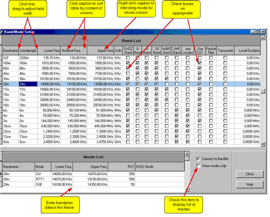
The Bands & Modes table can be accessed from the main menu sub item Edit and will come to the screen as below:
The screen consists of two parts: The upper part shows all bands which are defined in TurboLog 4. The lower part denoted as "Mode-List" contains mode assignments to bandsegments for the highlighted band. This essentially is the "bandplan" for this band. The bandplan will only be visible if the check box at the right side of the bandplan is checked for "Connect to Bandlist"
In case "Show modes only" is checked the lower part of the display will turn into a list which shows all modes defined in TurboLog 4. This is what comes to display:

Figure 80: The Modes List
All parameters which appear in these three displays will be presented in the next paragraphs:
Like any other data grid the Bands & Modes tables can be printed. The Print command is available from the context menu which pops up on right mouse key click.
BANDNAME:
This is the name which TurboLog 4 uses as entry of the Band field on the loginput line. It corresponds to the nominal wavelength of this band.
WAVELENGTH:
This is the physical representation of an electromagnetic wave of a distinct frequency radiated in free space. Since the ham radio bands are defined by frequency intervals the associated wavelength is typically a rounded value from a frequency within the band or near by. In most cases bandname and wavelength will be equivalent. As shown in the first line of the display, however, you can assign other notations as well. In this case "VLF" ( = Very Low Frequency ) was chosen as bandname for a wavelength of 2200m. You can change this assignment if you want. Here is the place to do it.
NOMINAL FREQUENCY:
You might not want to print the exact operating frequency on your QSL card in order to save some space, nevertheless you prefer a short frequency notation to be used, if so then this is important for you. The nominal frequency likewise represents the notation for a band. It is typically chosen as a rounded value from the upper/lower bandlimits or from somewhere in the centre of the band. Here is to change it according to your needs.
LOWER FREQUENCY:
This entity denotes the lower frequency edge of a band. You may need to adjust it to your regional or national legislation.
UPPER FREQUENCY:
This entity denotes the upper frequency edge of a band. You may need to adjust it to your regional or national legislation.
UNITS:
This column contains the physical dimension of the frequencies defined as above. It will be mostly KHz, MHz and GHz. There should be no need to change it.
VHF BAND:
This field should be checked if you want the band to belong to the VHF group...or better say not to belong to the group of HF bands.
Checking this field indicates the band belongs to those bands that are part of the DXCC award program as defined by the ARRL's DXCC desk.
6 BAND:
Checking this field assigns the band to belong to the classic 6 HF bands....160m, 80m, 40m, 20m, 15m and 10m. This is an important feature for the DXCC awards program.
9 BAND:
Checking this field assigns the band to belong to the 9 HF bands....160m, 80m, 40m, 30m, 20m, 17m, 15m, 12m and 10m. This is an important feature for the DXCC awards program.
10 BAND:
Checking this field assigns the band to belong to the group of the 9 HF bands plus 6m. This is an important feature for the DXCC awards program ( 10 band challenge ).
WARC BAND:
The 3 WARC bands ( 30m, 17m and 12m ) are identified by checking this field.
USE LOCATOR:
This field should be checked if you want the gridsquare locator to become an essential log entry for this band. This is of interest for those collecting locators and for reports and displays in TurboLog 4.
USE CAT:
Check this field if you want to use CAT on this band.
PACKET FILTER:
Check this field if you want to run band specific packet filters for this band.
TRANSVERTER:
This field needs to be checked if you intend to run a transverter on this band. The target band needs to be checked as well since TurboLog 4 needs to know the corresponding bands for proper operation.
Both bands need to be provided with a suitable Local Oscillator frequency as described below.
LOCAL OSCILLATOR:
If you plan to use a transverter on this band you need to define the local oscillator frequency here. A positive sign on the frequency offset indicates: This is the base band. Consequently the target band needs to be provided with the same frequency offset but with negative sign. The local oscillator frequency is typically the difference of the frequencies of the lower edges of the target band and the base band.
See paragraph below on commands for editing the content of the band list.
This list defines band segments in terms of their lower and upper frequency limits. The mode recommended by the international regulation authorities is assigned to this segment. If you run " Auto Mode " and QSY into this segment the mode will automatically be changed to the mode defined in this list for this particular segment.
Of course you can customize these definitions. You can enter as many band segments and mode assignments as you want.
Please note, however, only one mode can be assigned to a particular frequency or frequency band.
Along with the mode goes the report definition, i.e. whether the default report contains 3 numbers ( 599 ) or just 2 ( 59 ).
All captions are identical to those above, except for DXCC mode which needs to be edited in the list of modes that is described in the paragraph below.
See paragraph below for commands.
The list of Modes:
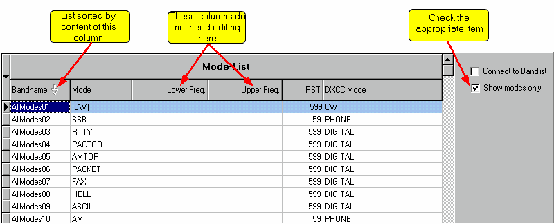
Currently the list of modes available in TurboLog 4contains 17 entries. As described above this list can be accessed for editing or inspection by selecting checkbox " Show modes only ". The first 10 entries of the list of modes are depicted below:

Figure 81: The Modes List
Every mode is defined by a unique notation "AllModes01"......"AllModes17". The column "Bandname" is slightly abused to contain these definitions. The arrow directed downwards indicates that the whole list is sorted by the entries of this column.
The "Mode" column contains the real name of the Mode. The default mode to appear on the loginput line is defined here. It has to be bracketed in rectangular brackets for just this purpose. Of course you can reassign the default to any other mode of your choice by simply editing the fields accordingly.
The "RST" column contains the default report configuration for the selected mode.
The "DXCC Mode" is assigned in the rightmost column. Currently there are 4 DXCC Modes defined by the ARRL. This is the spot to edit the definitions and to assign the correct DXCC Mode to the real mode.
If you wanted to include a new mode to the list of the 17 modes it should be inserted as "AllMode18" at the bottom of the list. See below for commands.
Please note:
This list is the spot to define the start-up Mode to appear on the loginput line. The [...]-bracketed Mode ...CW in this case... is defined as the start-up value to be initially shown on the loginput line. It will appear as such on the list of the Default Stack for the Mode's entry field on the loginput line. However, the start-up Mode cannot effectively altered there .... only here!
Customizing the Band-List/Mode-List:
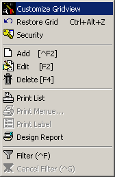
A right-mouse-key click on anyone of the entries will surface the following context menu:

Figure 82: Context Menu
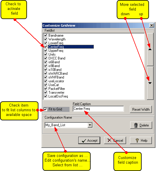
Clicking the selected item Customize Gridview results in displaying the following frame:

Figure 83: Customizing the Bands & Modes Table
This frame is very similar to the display constructed for customizing the loginput line. If Fit to Grid is checked the program will try to best fit the columns selected for display to the available space in the band list. This fit is for the current session only unless you leave the frame with the box checked, enter the frame again, uncheck and leave. To revert to the factory default settings, press the Reset Width button.
Every selected input field will automatically appear with its caption on the header line of the tables.
Click the Accept button to save your modifications under the selected name or click the Cancel button to leave the frame without making permanent changes. Clicking the Delete button will open a dialogue on whether you really want to delete the selected configuration and remove its name from the list.
If you want to create a new configuration you start from anyone of the defaults, making field arrangements according to your needs and finally edit the selected name to whatever makes sense to you. Click Accept in order to save the new configuration under this name. Your customized list will immediately be activated.
Editing the lists:
Please note:
All editing operations for the lists and tables a fully compliant with WINDOWS standards.
Please further note:
All editing of the Bands&Modes tables becomes effective right away after finishing and closing the tables.
The most important key and mouse actions are summarized below:
KEYS:
| EDIT | F2-key, or right mouse key click for context menu |
| INSERT | Inserts a new row above highlighted row. |
| DELETE | Deletes a selected field. |
| Ctrl+DELETE | Deletes the whole row. You are prompted before execution. |
MOUSE:
| LEFT KEY CLICK | on row: Selects/highlights this particular row. |
| LEFT KEY CLICK | on highlighted field: Opens field for editing...or....inverts the status of a checkbox field. |
| LEFT KEY CLICK | on separator of caption: Starts drag mode to adjust field width. |
| LEFT KEY CLICK | on caption: Selects column and its content for sorting whole table. |
| RIGHT KEY CLICK | on caption: Starts drag mode to move whole column. |
| RIGHT MOUSE KEY | over grid: Pops up context menu |
BUTTONS:
| DELETE | Deletes selected item, prompts before execution. |
| ACCEPT | Accepts selected configuration. |
| CANCEL | Cancels all changes and editing made so far. |
| CLOSE | Closes focussed frame. |
| HELP | Opens (this) help window. |
| RESET WIDTH | Resets field widths to factory defaults. |
| FIT TO GRID | Arranges columns to best fit to window size. |
This topic was last edited on Monday, 03-Jul-2023, at 23:56
